Part 2: Drawing the lattice
To make a drawing of the lattice that can be directly translated to Zacros one can follow these steps:
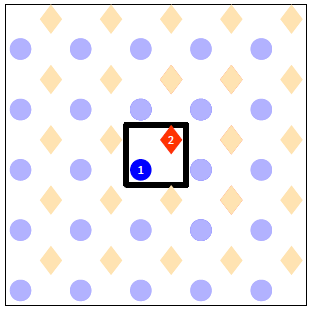
- Draw the unit cell with all sites therein.
It is advisable to use different markers or colours to denote the different site types. For our lattice, the drawing after this step would contain the square with the thick line and the sites with the vivid colours as displayed below. The blue circles denote the atop sites and the orange diamonds the 4-fold hollow. To show how the lattice would look like when this unit cell is tiled on the plane we have also drawn many more sites around the unit cell in pale colours.

- Number all the sites within the unit cell.
We have two sites inside our unit cell, which will be numbered as 1 for the atop and 2 for the hollow. If there were more than one sites of the same type, for instance two atop sites, we would have to assign a different number to each site, so we could have site number 1 being atop, site number 2 being atop, site number 3 being hollow etc. At the end of this step our drawing looks like the following:
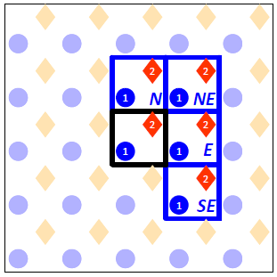
- Draw periodic images of the unit cell clockwise starting from the North neighbour (marked N) to the SouthEast neighbroud (marked SE).
This is in preparation to the next step, in which we will be drawing the links between the connected sites. Note that due to symmetry we do not need to specify any links with the remaining 4 neighbours (South to NorthWest). For instance, if site 1 at the Central cell neighbours with site 2 at the North cell, it follows that site 2 at the Central cell will neighbour with site 1 at the South cell. At the end of this step our drawing looks like this:
- Mark all links between the sites of the central cell with the sites of the neighbouring cells.
In our case we have a total of 8 links: the atop site of the Central cell connects with the atop sites of the North and East neighbours; similarly the hollow site of the Central cell connects with the hollow sites of the North and East neighbours. Also, the hollow site at the Central cell is connected with the atop site in that same cell and the atop sites of three neighbours. At the end of this step our drawing looks as shown below (note that we have dropped the designations N, NE, E and SE of the four neighbouring cells to avoid cluttering the picture):
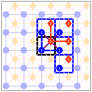
In the next section we will see how the above figure can be translated to a lattice_input.dat file that can be parsed by Zacros.